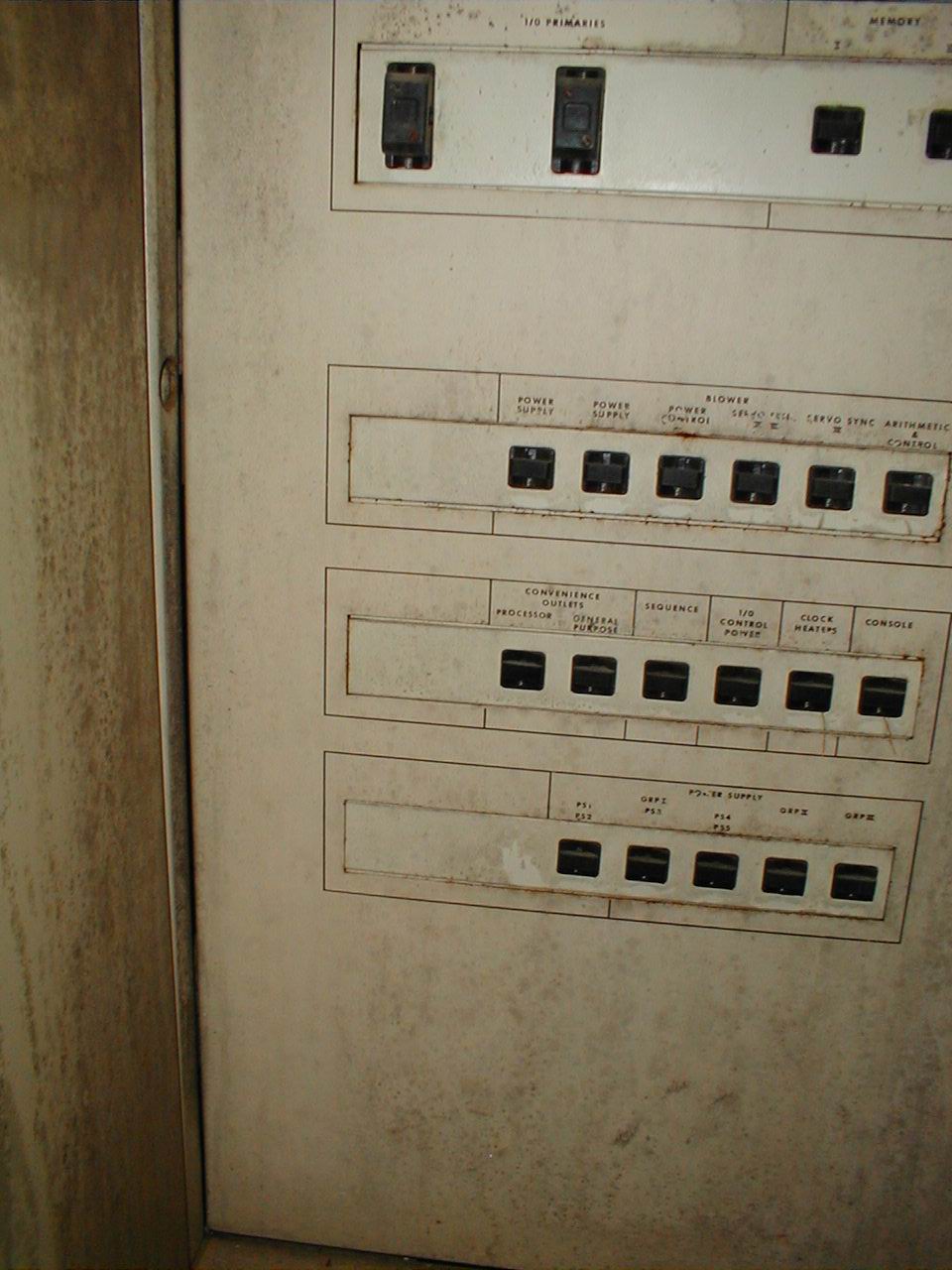
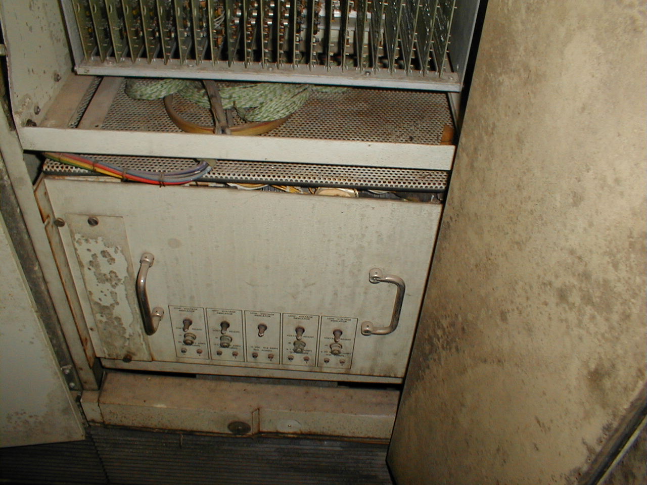
 P1010027.JPG power supply breaker panel. this is view of panel area below the status lights, and time meter |
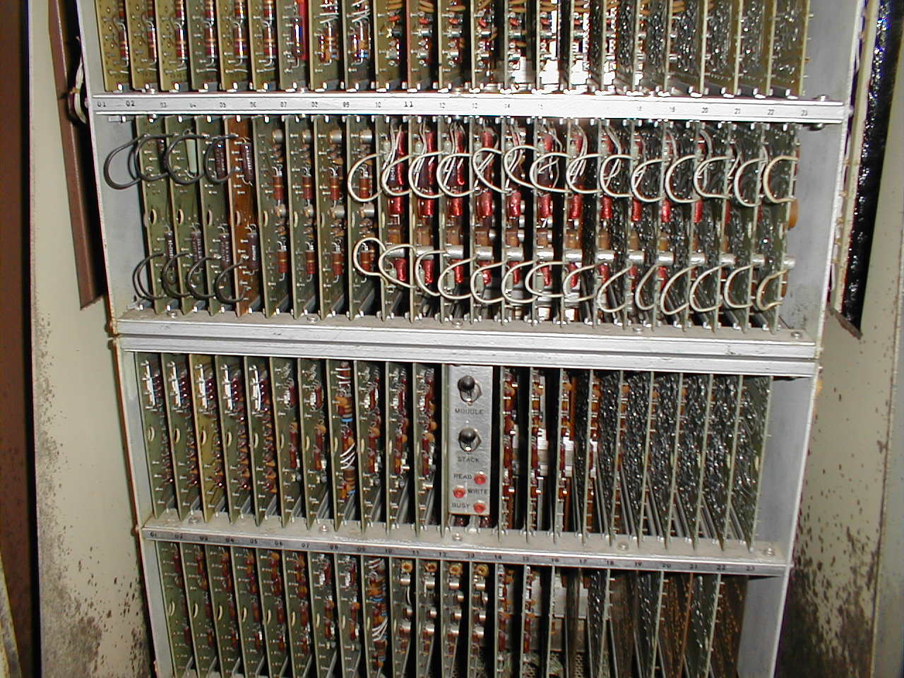
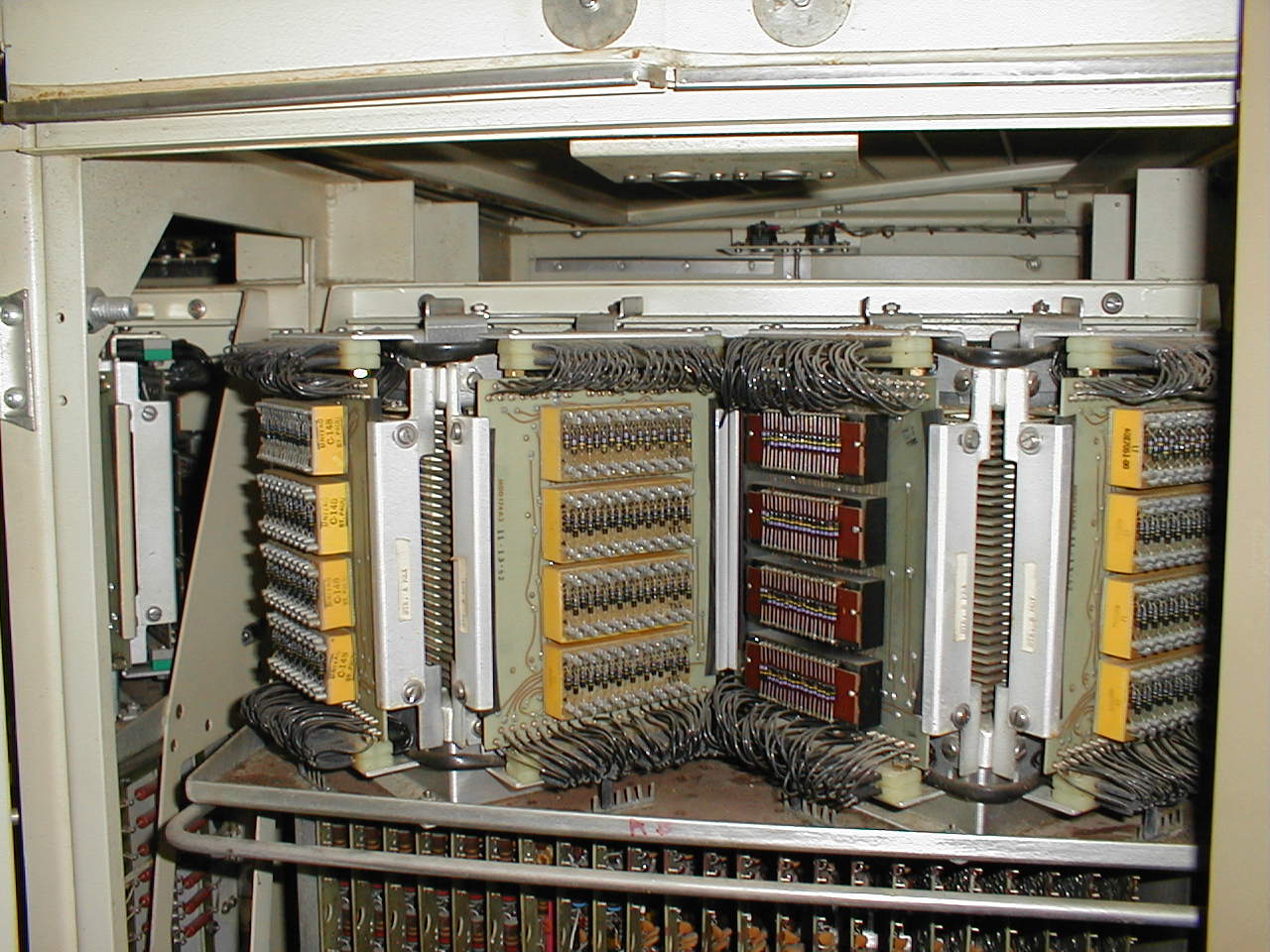 P1010028.JPG one core stack. There are two of these in each bay, and this system has two bays for total of 4 stacks. It is belived currently this means system has 32k x 28 bits memory |
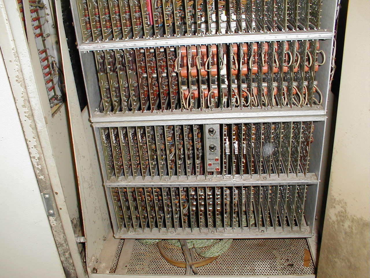 P1010029.JPG logic below the right core stack below core stack |
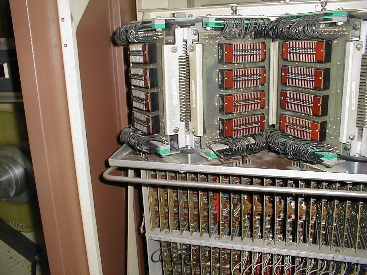 P1010030.JPG close up of one of the core stacks. there should be X, Y, and inhibit, but not known for now which that is in this system. |
 P1010031.JPG left core logic bay below core stack |
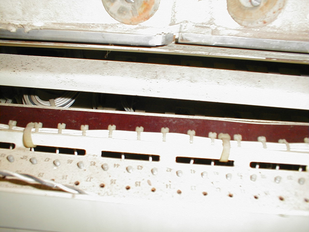
 P1010032.JPG bottom of core stack bay, right hand mostly trim for power supply feeds |
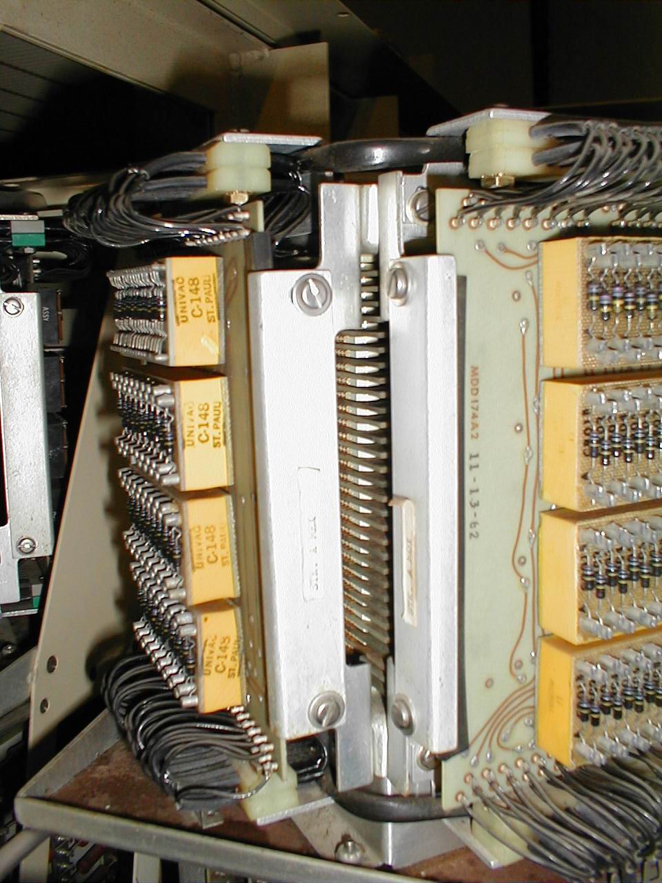 P1010033.JPG manufacture date, on right board, 11-13-62 where were you? |
 P1010034.JPG This shot was takend after pulling the front panel out (this is the processor control panel) |
Page: 1 2 3 4 5